1
2
3
4
5
6
import pyrtl
r = pyrtl.Register(4, reset_value=2)
r.next <<= r + 1
o = pyrtl.Output(4, 'o')
o <<= r
10 Jun 2021
We recently added support for generating register reset logic in the Verilog design that you produce from PyRTL.
This is opposed to the Verilog test bench that PyRTL produces, which already supports adding initial values, extra logically, in the initial blocks.
In the post, we’ll talk about reset logic, which is needed for bringing up a system in a predictable state and is thus an important and unique part of the synthesis process. In particular, synthesis tools rely on being able to detect resets being used in particular ways in order to generate the correct designs that best take advantage of the target devices.
Here's the outline of what we'll be covering:
An Example
Let’s start with a small PyRTL example: a 4-bit counter:
reset_value in line 3 is a new flag for specifying the reset value of the given register.
We can print it out to GraphViz and use
dot to produce a PNG:with open("counter.gv", "w") as f:
pyrtl.output_to_graphviz(f)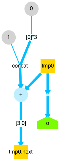
Note that the graph looks the same as normal; no reset wire has been inserted into the design.
This new feature, the reset_value flag in the Register initializer, instead affects two things:
-
Simulation
-
Verilog Output
For Simulation, the main thing to know is that each individual register’s reset_value, if specified, will be used for initialization at the start of the simulation, unless overridden via other simulation flags.
The more interesting part, however, and the topic of the rest of this post, is about synthesis of reset logic by third-party tools.
Synthesis
If we run the following:
with open("counter_sync_reset.v", "w") as f:
    pyrtl.output_to_verilog(f)
PyRTL produces the following Verilog:
1
2
3
4
5
6
7
8
9
10
11
12
13
14
15
16
17
18
19
20
21
22
23
24
25
26
27
28
29
30
31
32
33
34
35
36
37
38
39
// Generated automatically via PyRTL
// As one initial test of synthesis, map to FPGA with:
// yosys -p "synth_xilinx -top toplevel" thisfile.v
module toplevel(clk, rst, o);
input clk;
input rst;
output[3:0] o;
reg[3:0] r;
wire const_0_1;
wire const_1_0;
wire[2:0] tmp0;
wire[3:0] tmp1;
wire[4:0] tmp2;
wire[3:0] tmp3;
// Combinational
assign const_0_1 = 1;
assign const_1_0 = 0;
assign o = r;
assign tmp0 = {const_1_0, const_1_0, const_1_0};
assign tmp1 = {tmp0, const_0_1};
assign tmp2 = r + tmp1;
assign tmp3 = {tmp2[3], tmp2[2], tmp2[1], tmp2[0]};
// Registers
always @(posedge clk)
begin
if (rst) begin
r <= 2;
end
else begin
r <= tmp3;
end
end
endmodule
In lines 5 and 7 we add the rst input wire.
In line 31 we conditionally update r based on if rst is high, to the value 2 (in line 32).
As you can see, the logic we have created updates the register synchronously.
By including only clk in the sensitivity list, the block that follows is only triggered on the positive edge.
By checking rst only inside the block, we can update our register to our reset_value, 2, when rst is high and we’re on a clock edge.
Let’s synthesize this to Xilinx, like the header of the produced file suggests [1]:
$ yosys -p "synth_xilinx -top toplevel -blif counter_xilinx_sync.blif" counter_sync_reset.vLet’s take a look at the BLIF file Yosys produced:
# Generated by Yosys 0.9+2406 (git sha1 aee43936, clang 11.0.3 -fPIC -Os)

.model toplevel
.inputs clk rst
.outputs o[0] o[1] o[2] o[3]
.names $false
.names $true
1
.names $undef
.subckt INV I=r[0] O=$auto$alumacc.cc:485:replace_alu$1386.S[0]
.subckt CARRY4 CI=$false CO[0]=$auto$alumacc.cc:485:replace_alu$1386.C[0] CO[1]=$auto$alumacc.cc:485:replace_alu$1386.C[1] CO[2]=$auto$alumacc.cc:485:replace_alu$1386.C[2] CO[3]=$auto$alumacc.cc:485:replace_alu$1386.C[3] CYINIT=$false DI[0]=$true DI[1]=$false DI[2]=$false DI[3]=$false O[0]=tmp3[0] O[1]=tmp3[1] O[2]=tmp3[2] O[3]=tmp3[3] S[0]=$auto$alumacc.cc:485:replace_alu$1386.S[0] S[1]=r[1] S[2]=r[2] S[3]=r[3]
.subckt BUFG I=$auto$clkbufmap.cc:247:execute$1555 O=$iopadmap$clk
.subckt FDRE C=$iopadmap$clk CE=$true D=tmp3[0] Q=r[0] R=$iopadmap$rst (1)
.subckt FDSE C=$iopadmap$clk CE=$true D=tmp3[1] Q=r[1] S=$iopadmap$rst (2)
.subckt FDRE C=$iopadmap$clk CE=$true D=tmp3[2] Q=r[2] R=$iopadmap$rst (3)
.subckt FDRE C=$iopadmap$clk CE=$true D=tmp3[3] Q=r[3] R=$iopadmap$rst (4)
.subckt IBUF I=clk O=$auto$clkbufmap.cc:247:execute$1555
.subckt OBUF I=r[0] O=o[0]
.subckt OBUF I=r[1] O=o[1]
.subckt OBUF I=r[2] O=o[2]
.subckt OBUF I=r[3] O=o[3]
.subckt IBUF I=rst O=$iopadmap$rst
.names r[1] $auto$alumacc.cc:485:replace_alu$1386.S[1]
1 1
.names r[2] $auto$alumacc.cc:485:replace_alu$1386.S[2]
1 1
.names r[3] $auto$alumacc.cc:485:replace_alu$1386.S[3]
1 1
.names $true const_0_1
1 1
.names $false const_1_0
1 1
.names $false tmp0[0]
1 1
.names $false tmp0[1]
1 1
.names $false tmp0[2]
1 1
.names $true tmp1[0]
1 1
.names $false tmp1[1]
1 1
.names $false tmp1[2]
1 1
.names $false tmp1[3]
1 1
.names tmp3[0] tmp2[0]
1 1
.names tmp3[1] tmp2[1]
1 1
.names tmp3[2] tmp2[2]
1 1
.names tmp3[3] tmp2[3]
1 1
.names $undef tmp2[4]
1 1
.end
Take a look at the lines labelled 1-4 (on the right edge of the code listing). According to the Xilinx 7 Series FPGA Libraries Guide, there are dozens of types of flip flops Xilinx provides. We are only concerned with two of them right now:
-
FDRE, the D Flip Flop with Clock Enable and Synchronous Reset -
FDSE, the D Flip Flop with Clock Enable and Synchronous Set
In each of those labelled lines above, the R formal terminals are connected to $iopadmap$rst,
This latter signal is connected to our original rst input signal via an input buffer IBUF.
Similarly, the synthesis has correctly identified the clock, clk, which is connected via a Global Clock Simple Buffer (BUFG) to $iopadmap$clk, which in turn is connected to the C formal terminals of the above labelled lines.
The thing we’re interested in, though, are the types of flip flops used (repeated here for convenience):
.subckt FDRE C=$iopadmap$clk CE=$true D=tmp3[0] Q=r[0] R=$iopadmap$rst
.subckt FDSE C=$iopadmap$clk CE=$true D=tmp3[1] Q=r[1] S=$iopadmap$rst
.subckt FDRE C=$iopadmap$clk CE=$true D=tmp3[2] Q=r[2] R=$iopadmap$rst
.subckt FDRE C=$iopadmap$clk CE=$true D=tmp3[3] Q=r[3] R=$iopadmap$rst
We have two synchronous reset flip flop in the top two MSBs (going to r[3] and r[2]), then a synchronous set flip flop (going to r[1]), then finally another synchronous reset flip flop in the LSB (going to r[0]).
Thus, we have the concatenation of reset,reset,set,reset, or more succinctly, 0b0010, which is 2, equivalent to the reset_value we specified in PyRTL and saw in the Verilog.
Asynchronous Reset
What about asynchronous reset?
Well, PyRTL supports generating Verilog with asynchronous reset also:
with open("counter_async_reset.v", "w") as f:
    pyrtl.output_to_verilog(f, add_reset='asynchronous')
That will produce the following Verilog:
1
2
3
4
5
6
7
8
9
10
11
12
13
14
15
16
17
18
19
20
21
22
23
24
25
26
27
28
29
30
31
32
33
34
35
36
37
38
39
// Generated automatically via PyRTL
// As one initial test of synthesis, map to FPGA with:
// yosys -p "synth_xilinx -top toplevel" thisfile.v
module toplevel(clk, rst, o);
input clk;
input rst;
output[3:0] o;
reg[3:0] r;
wire const_0_1;
wire const_1_0;
wire[2:0] tmp0;
wire[3:0] tmp1;
wire[4:0] tmp2;
wire[3:0] tmp3;
// Combinational
assign const_0_1 = 1;
assign const_1_0 = 0;
assign o = r;
assign tmp0 = {const_1_0, const_1_0, const_1_0};
assign tmp1 = {tmp0, const_0_1};
assign tmp2 = r + tmp1;
assign tmp3 = {tmp2[3], tmp2[2], tmp2[1], tmp2[0]};
// Registers
always @(posedge clk or posedge rst)
begin
if (rst) begin
r <= 2;
end
else begin
r <= tmp3;
end
end
endmodule
The main difference is in line 29 above. Here, the block is triggered on the positive edge of either the clock or the reset signal.
Importantly,
yosys is also able to recognize this when synthesizing down to Xilinx:$ yosys -p "synth_xilinx -top toplevel -blif counter_xilinx_async.blif" counter_async_reset.vThis produces the following BLIF:
# Generated by Yosys 0.9+2406 (git sha1 aee43936, clang 11.0.3 -fPIC -Os)

.model toplevel
.inputs clk rst
.outputs o[0] o[1] o[2] o[3]
.names $false
.names $true
1
.names $undef
.subckt INV I=r[0] O=$auto$alumacc.cc:485:replace_alu$1383.S[0]
.subckt CARRY4 CI=$false CO[0]=$auto$alumacc.cc:485:replace_alu$1383.C[0] CO[1]=$auto$alumacc.cc:485:replace_alu$1383.C[1] CO[2]=$auto$alumacc.cc:485:replace_alu$1383.C[2] CO[3]=$auto$alumacc.cc:485:replace_alu$1383.C[3] CYINIT=$false DI[0]=$true DI[1]=$false DI[2]=$false DI[3]=$false O[0]=tmp3[0] O[1]=tmp3[1] O[2]=tmp3[2] O[3]=tmp3[3] S[0]=$auto$alumacc.cc:485:replace_alu$1383.S[0] S[1]=r[1] S[2]=r[2] S[3]=r[3]
.subckt BUFG I=$auto$clkbufmap.cc:247:execute$1548 O=$iopadmap$clk
.subckt FDCE C=$iopadmap$clk CE=$true CLR=$iopadmap$rst D=tmp3[0] Q=r[0] (1)
.subckt FDPE C=$iopadmap$clk CE=$true D=tmp3[1] PRE=$iopadmap$rst Q=r[1] (2)
.subckt FDCE C=$iopadmap$clk CE=$true CLR=$iopadmap$rst D=tmp3[2] Q=r[2] (3)
.subckt FDCE C=$iopadmap$clk CE=$true CLR=$iopadmap$rst D=tmp3[3] Q=r[3] (4)
.subckt IBUF I=clk O=$auto$clkbufmap.cc:247:execute$1548
.subckt OBUF I=r[0] O=o[0]
.subckt OBUF I=r[1] O=o[1]
.subckt OBUF I=r[2] O=o[2]
.subckt OBUF I=r[3] O=o[3]
.subckt IBUF I=rst O=$iopadmap$rst
.names r[1] $auto$alumacc.cc:485:replace_alu$1383.S[1]
1 1
.names r[2] $auto$alumacc.cc:485:replace_alu$1383.S[2]
1 1
.names r[3] $auto$alumacc.cc:485:replace_alu$1383.S[3]
1 1
.names $true const_0_1
1 1
.names $false const_1_0
1 1
.names $false tmp0[0]
1 1
.names $false tmp0[1]
1 1
.names $false tmp0[2]
1 1
.names $true tmp1[0]
1 1
.names $false tmp1[1]
1 1
.names $false tmp1[2]
1 1
.names $false tmp1[3]
1 1
.names tmp3[0] tmp2[0]
1 1
.names tmp3[1] tmp2[1]
1 1
.names tmp3[2] tmp2[2]
1 1
.names tmp3[3] tmp2[3]
1 1
.names $undef tmp2[4]
1 1
.end
I’ve again labelled the important parts.
In the lines labelled 1, 3, and 4, it’s using a FDCE, while in line 2, it’s using a FDPE.
Going back to the Xilinx manual, we learn that:
-
FDCEis the D Flip Flop with Clock Enable and Asynchronous Clear -
FDPEis the D Flip Flop with Clock Enable and Asynchronous Preset
This is again equal to 0b0010 if we stare closely enough, i.e. our expected reset_value.
Non-Xilinx Synthesis
If you use
yosys to remove the .subckt instances via the techmap pass and thus be more generic, we get the following (only including the pertinent snippet):.gate $_DFF_PP0_ C=clk D=tmp3[0] Q=tmp0[0] R=rst
.gate $_DFF_PP1_ C=clk D=tmp3[1] Q=tmp0[1] R=rst
.gate $_DFF_PP0_ C=clk D=tmp3[2] Q=tmp0[2] R=rst
.gate $_DFF_PP0_ C=clk D=tmp3[3] Q=tmp0[3] R=rstAccording to Chapter 5 of the Yosys manual:
The cell types
$DFF_Nand$DFF_Prepresent d-type flip-flops.The cell types
$DFF_NN0,$DFF_NN1,$DFF_NP0,$DFF_NP1,$DFF_PN0,$DFF_PN1,$DFF_PP0and$DFF_PP1implement d-type flip-flops with asynchronous resets.
What About No Reset?
For the sake of completeness, let’s also look at what’s generated by PyRTL when we explicitly say we do not want to include reset logic:
with open("counter_no_reset.v", "w") as f:
    pyrtl.output_to_verilog(f, add_reset=False)
This produces the following Verilog:
1
2
3
4
5
6
7
8
9
10
11
12
13
14
15
16
17
18
19
20
21
22
23
24
25
26
27
28
29
30
31
32
33
34
35
// Generated automatically via PyRTL
// As one initial test of synthesis, map to FPGA with:
// yosys -p "synth_xilinx -top toplevel" thisfile.v
module toplevel(clk, o);
input clk;
output[3:0] o;
reg[3:0] r;
wire const_0_1;
wire const_1_0;
wire[2:0] tmp0;
wire[3:0] tmp1;
wire[4:0] tmp2;
wire[3:0] tmp3;
// Combinational
assign const_0_1 = 1;
assign const_1_0 = 0;
assign o = r;
assign tmp0 = {const_1_0, const_1_0, const_1_0};
assign tmp1 = {tmp0, const_0_1};
assign tmp2 = r + tmp1;
assign tmp3 = {tmp2[3], tmp2[2], tmp2[1], tmp2[0]};
// Registers
always @(posedge clk)
begin
begin
r <= tmp3;
end
end
endmodule
Finally, the BLIF that is produced after Xilinx synthesis:
# Generated by Yosys 0.9+2406 (git sha1 aee43936, clang 11.0.3 -fPIC -Os)

.model toplevel
.inputs clk
.outputs o[0] o[1] o[2] o[3]
.names $false
.names $true
1
.names $undef
.subckt INV I=r[0] O=$auto$alumacc.cc:485:replace_alu$1383.S[0]
.subckt CARRY4 CI=$false CO[0]=$auto$alumacc.cc:485:replace_alu$1383.C[0] CO[1]=$auto$alumacc.cc:485:replace_alu$1383.C[1] CO[2]=$auto$alumacc.cc:485:replace_alu$1383.C[2] CO[3]=$auto$alumacc.cc:485:replace_alu$1383.C[3] CYINIT=$false DI[0]=$true DI[1]=$false DI[2]=$false DI[3]=$false O[0]=tmp3[0] O[1]=tmp3[1] O[2]=tmp3[2] O[3]=tmp3[3] S[0]=$auto$alumacc.cc:485:replace_alu$1383.S[0] S[1]=r[1] S[2]=r[2] S[3]=r[3]
.subckt BUFG I=$auto$clkbufmap.cc:247:execute$1548 O=$iopadmap$clk
.subckt FDRE C=$iopadmap$clk CE=$true D=tmp3[0] Q=r[0] R=$false (1)
.subckt FDRE C=$iopadmap$clk CE=$true D=tmp3[1] Q=r[1] R=$false (2)
.subckt FDRE C=$iopadmap$clk CE=$true D=tmp3[2] Q=r[2] R=$false (3)
.subckt FDRE C=$iopadmap$clk CE=$true D=tmp3[3] Q=r[3] R=$false (4)
.subckt IBUF I=clk O=$auto$clkbufmap.cc:247:execute$1548
.subckt OBUF I=r[0] O=o[0]
.subckt OBUF I=r[1] O=o[1]
.subckt OBUF I=r[2] O=o[2]
.subckt OBUF I=r[3] O=o[3]
.names r[1] $auto$alumacc.cc:485:replace_alu$1383.S[1]
1 1
.names r[2] $auto$alumacc.cc:485:replace_alu$1383.S[2]
1 1
.names r[3] $auto$alumacc.cc:485:replace_alu$1383.S[3]
1 1
.names $true const_0_1
1 1
.names $false const_1_0
1 1
.names $false tmp0[0]
1 1
.names $false tmp0[1]
1 1
.names $false tmp0[2]
1 1
.names $true tmp1[0]
1 1
.names $false tmp1[1]
1 1
.names $false tmp1[2]
1 1
.names $false tmp1[3]
1 1
.names tmp3[0] tmp2[0]
1 1
.names tmp3[1] tmp2[1]
1 1
.names tmp3[2] tmp2[2]
1 1
.names tmp3[3] tmp2[3]
1 1
.names $undef tmp2[4]
1 1
.end
Note how in lines labelled 1-4, the argument for R is always $false.
There is no reset logic associated with those synchronous D flip flops.
Further Information
As we primarily focused on Xilinx in the post, you might find it useful to read this short blog post about demystifying resets.